- Resources
Here are some preliminary results for a spectral simulator designed to test the capabilities and differences between SDA, PCA , and NMF on simulated optical plume spectral data.
Background:
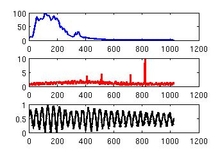
The original signal has been designed to have features both in the spectral domain and in the time domain. It has been divided up into 3 Components. The first is the dominant spectral component that grows at a steady exponential rate over time. The 2nd component has spectral peaks that correspond to the presence of chromium burning in a liquid rocket engine such as the SSME. This component also grows at an exponential rate but towards the end has a steeper exponential growth. We are interested in this component both in identifying the spectral features but also accurately identifying the time profile. The 3rd component is at the noise level and has a fairly constant contribution over time. The time component and spectral components were linearly combined in this manner:
Where A is the time components and is a pxN matrix
Where S is the spectral components and is a Nxm matrix
and LaTeX where Y is a p xm matrix.
Method:
PCA and SDA were applied to the Y matrix to decompose the A and S components. Since the A and S matrices are known it is easy to judge the performance of the feature decomposition techniques. In each figure the root mean squared error is displayed. The first 2 figures show the first 2 Spectral components for PCA and SDA. As you can see they are similar and match the original signal fairly closely. Figures 3 and 4 are the time components for the PCA and SDA. The first component matches very nicely but the 2nd component has some problems. Since the spectral components were matching very well they were used to initialization the spectral matrix for NMF. When running NMF the sparseness parameter on the spectral matrix was set to 0.75 and the number of components computed was 50. Since the component order for NMF is random the spectral components from PCA and SDA were used to identify the resulting spectral components from NMF. Once the spectral components were matched up the corresponding time components were found. The time components from the PCA and SDA initialized NMF can be seen in figures 5 and 6 respectively.
Updates 4-1-08:
Simulator Update:
The current simulator design has been changed to better represent elemental burns at a sparse intermittent rate. The 7th figure shows the intermittent time components for a sample elemental burn and the corresponding spectral features for that component. The spectral lines behave in a way were they will have a dominate wavelength for a given element and secondary peaks at other wavelengths as illustrated in the 7th figure. Individual element profiles for severity one elements, which had been identified by domain experts, are created for each component and normalized to have unit energy for the time frequency domain. The elements are then scaled to have a very small percentage before summing the elemental contributions in the time frequency domain. The remaining percentage of the burn is the dominate OH component accounting for over 99%. This is added with the subtotal from the element contribution. This process allows us to know what the true contribution of each component is for the entire run.
Analysis:
The initial analysis method is the same as before. SDA and PCA components are computed and used to initialize the NMF spectral matrix. The results from this process did not work as well as the previously simulated data. The problems occurred when decomposing the individual elemental components. The dominate OH burn was clearly removed however some spectral lines were overlapping between the remaining elemental spectral components. The time domain components were also showing similar blending results. Upon further inspection the SDA and PCA spectral components were not separating the elemental features in the new simulated data, which gives NMF a poor initialization.
The next logical step would be to prime NMF with the desired elemental features. The structure for the spectral component initialization was set up to be a vector with size N x m. Where N is the number of elemental components and m is the number of spectra. Each component vector was set to zero except for the corresponding wavelength bins for each element, which were set to one. This produced very nice separation of the elemental components in time. However one problem with NMF is that to get out a smooth time component the spectral components need to be sparse, which results in a fairly unusable spectrum. Since integrating domain information seemed to yield good results with NMF the next step was to apply the domain knowledge to SDA.
SDA was run uninitialized to remove the dominate OH component and leave the remaining elemental components in the residual. The same initialization matrix as in the NMF process was then used to initialize the SDA algorithm and decompose the remaining elemental components on the residual. This would extract each spectral feature one by one and then subtract out their contributions each time, leaving a new residual for the remaining components. The results compared to the original components can be seen in the 8th and 9th figures. This method seems to work very well with the new simulated data.
Attachments
Discussions
Popular Resources
Nothing to see here at the moment. Check back later.


